
Btw, I left twitter after Musk’s takeover, and can now be found on my own Mastodon server
————————————————-> INTERMISSION <—————————————————
So, what you may not know is that I spent all of 2022, developing a joystick controller from scratch.
About two years ago, from the writing of this post, I began playing Star Citizen. I did have it since 2014, however, I was never able to play it due to lacking computer (4fps looking at the ground of the hangar doesn’t count as playing, does it?) and I truly forgot about it, until some life developements brought me a powerhouse computer that could actually run it.
Of course, I got hooked immediately, and began picking up hardware. A cheap joystick…then went HOSAS with a second cheap joystick. Also got a headtracker, for wich I promptly modified it’s headpiece…you know the jazz.
But of course, cheap joysticks always end up in the trash, so to speak. The ones I got, let’s say where not the greatest ever made (altough they did have a particular set of characteristics that I liked from a modding perspective). So, I started looking at what the joystick landscape was offering.
And, surprise!, I didn’t like what I saw, and the rest is forgotten history. (go read the fucking subreddit if you want to know more).
ANYWAY.
I always thought myself as a HOSAS (Hands on Stick And Dick…I mean, Stick), since HOTAS (Hands on Throttle And Stick) had a strong dissapeal to me.
However, after finishing the joystick and using it extensively, I found out I really didn’t felt the need for another joystick, but rather, I would prefer an actual throttle.
Those come in two flavors, lever and linear.
Lever, as you can see below, moves the handle in an arc, twisting your wrist in doing so. I am definitely NOT a fan of that system, but it’s certainly easy to sense.
The linear type, as you should have already guessed, keeps your wrist and hand in the same position, and allows handle movement back and forth, wich also kinda feels more natural, but at the cost of greatly complicating your life when you want to know where the fuck the lever is.
So, of course, I ended up making my own (work in progress):

This throttle will have it’s own post when it’s ready (as will the joystick), but all this intro was required for you to understand the following bit.
So, as mentioned, this has a forward movement of 100mm, but how the heck do you sense that? My requirements were:
1: Easy absolute sensing. No encoders, mouse sensors, or LVDT’s.
2: Contactless-ish (no resistive types, wich rules out general potentiometers).
3: Easy to source (DiY doesn’t count, as long as materials are not weird AF)
With that in mind, as much as I would have loved to use inductive sensors, they are not super easy to use OR design yet, so I ended up thinking about making it hall sensed.
HOWEVER
I could not find for the life of me, a 100mm long, 2x1mm neodimium magnet that I could use to directly sense all the lenght. In retrospective, I am absolutely glad I could not find such magnet, because that led me in a weird and wonderful design path:
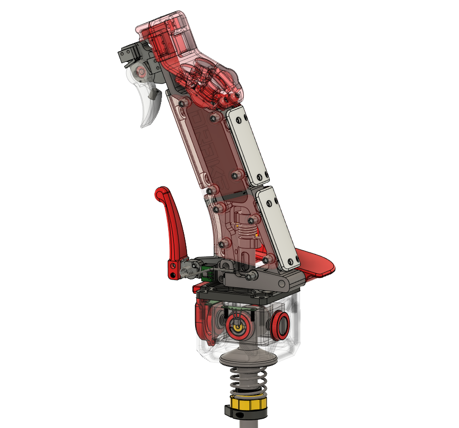
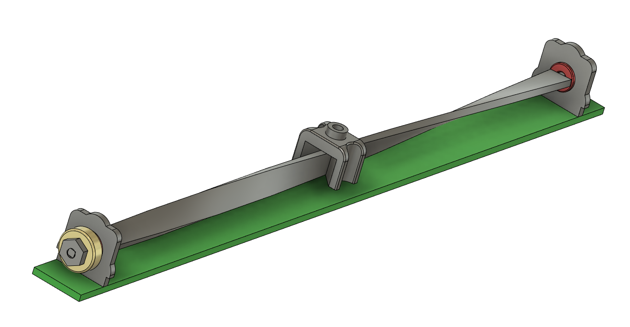
Wich ended up looking something like this:
It is very simple, actually. A twisted bar is attached to a diametrally magnetised neodimium ring (wich is read by a hall sensor) and a slider that barely makes contact (with PTFE inserts), moves along the lenght of the twisted bar, rotating it as it slides, and, as long as you don’t twist the bar past 180º, it will be an absolute sensor of the lenght.
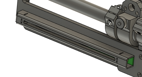
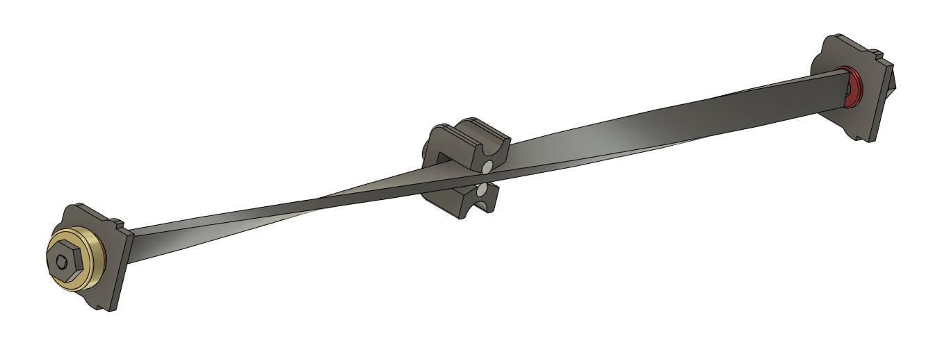
In the following image you can see a better view of the PTFE sliding surfaces over the twisted piece. The red blocks are not bushings, but actual miniature ball bearings (1.5x4x2mm, flanged)
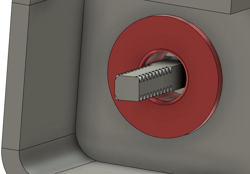
Attaching the twisted ribbon to the ends of the hall potentiometer, is made by threading the ends of the ribbon with an M1.4 nut, wich leaves a geometry like this (plenty strong for the aplication):
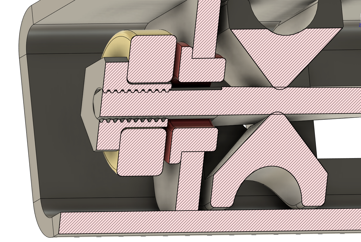
And a cross section of the assembly looks like this (missing a washer in between the bearing and magnet, I forgot to model it, and the slider is an older simplified version):
And now, it comes the moment of truth, can I actually build this shit? Keep in mind the hall linear potentiometer section measures 10x10mm (actually, 9.6×9.6mm*lenght) wich is not THAT dissimilar to other potentiometers in the same measurement region, wich means there is not that much space to fumble around.
Well, it seems the 1mm endmill can do what I asked (milling 0.8mm aluminium sheet) laser cutting would be better but I don’t have access to one.
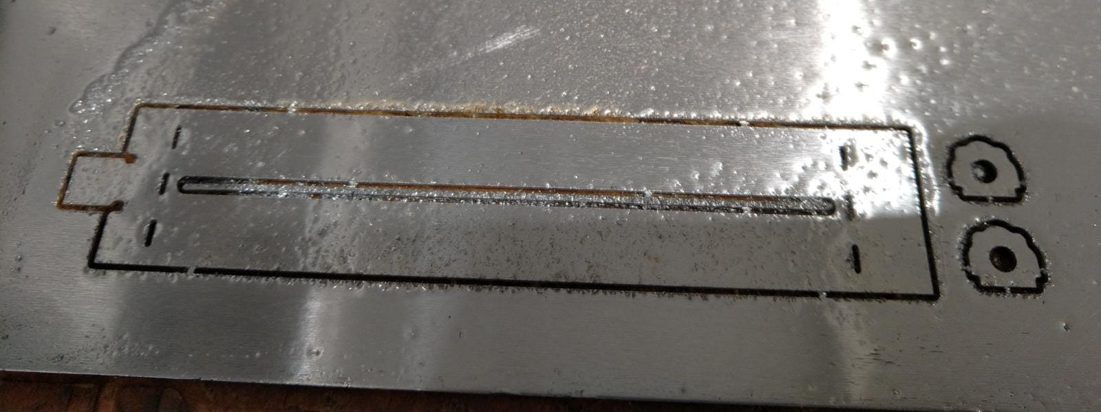
Postprocessed (background matt squares are 10mm per side). Twisting the ribbon can be acomplished with a pair of pliers (on aluminium).

After some bending trickery (and a pair of utter fails), I did get an useable piece I could test:
And now I can do my own custom hall linear potentiometers without depending on anyone.
Neat, right?
See you around!

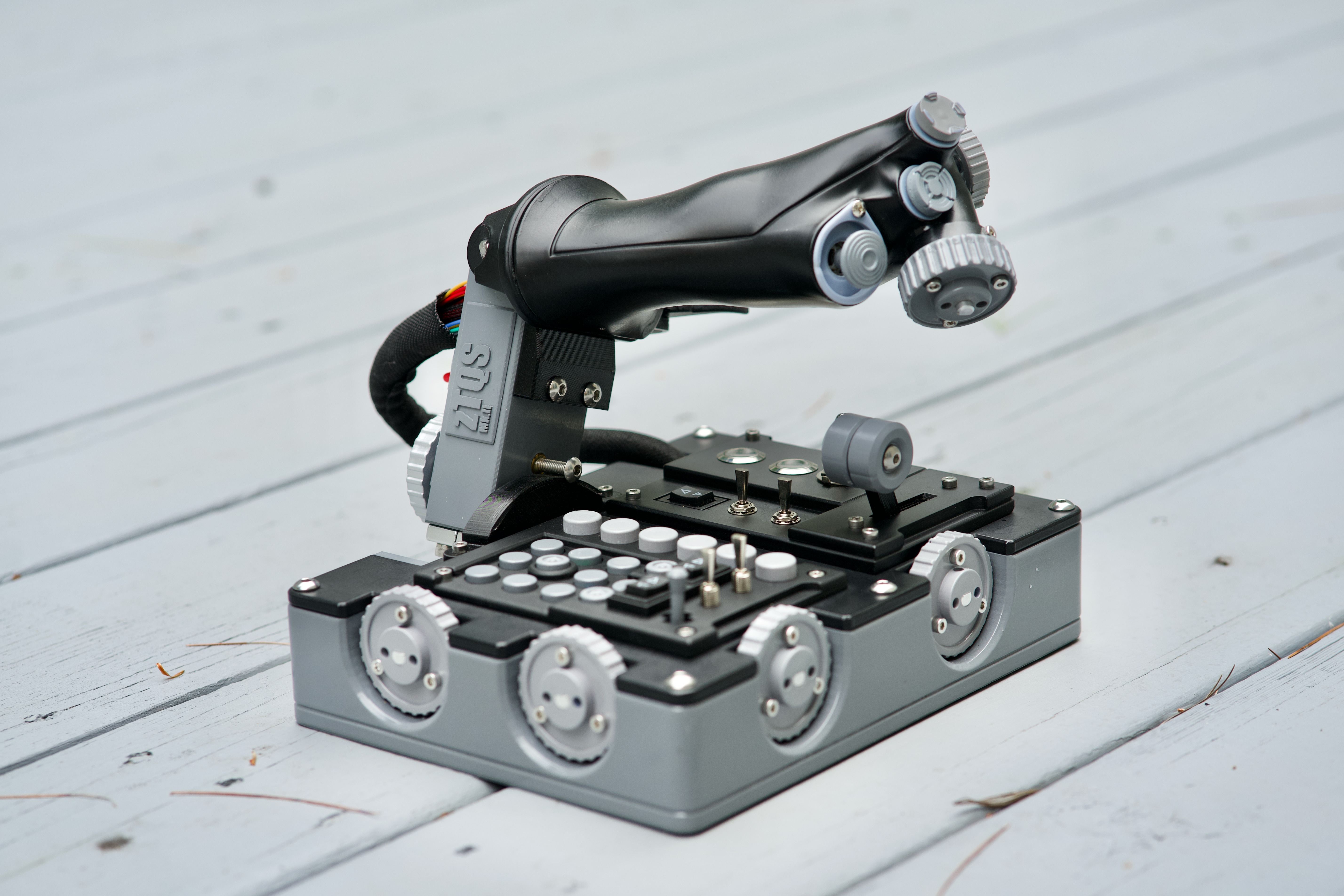
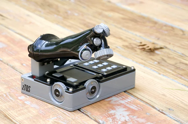
Maybe a silly question, but what are those two “zTQS” throttles? Are they renders/mockups?
There are NEVER silly questions if they come from the heart, don’t worry.
Those are real things (of pure beauty), made by someone named “Recoilfix” on reddit.
I wish my own looked this good, alas, I’m not so skilled.
Bravo, this is great! I had a similar idea but never took it as far as you did. For my own homemade fs yoke I ended up using a long rack and gear, but might have to give this a try! Seems like the accuracy of the bend would affect the linearity of the sensing, curious if you have any tricks to share on that?
So far, I have twisted the alu strip with a pair of tensioned pliers, but have not measured linearity, because I’m still figuring out how to do the casing (first time doing interlocking bent pieces (and the top slot doesn’t help at all) Once that’s under control, I’ll take a closer look at how to linearize the bend (IF making it under tension throws it overboard).
Two thoughts come to mind. The first are those Chinese calipers and linear scales. They are capacitive and ridiculously accurate. The second is 3xactly what you have there, but use a lead screw. I had a lead screw a long time ago that had about one twist per three or four inches. It even had a ball nut on it for zero backlash. If you put your magnet on the ball nut, you’d be golden. And it’s going to be solid and accurate. The third idea would be, get two precision rods and some nylon or polite bearings. Mount the slider on it. This breaks down into three possibilities. One, put a piece of something like ferrite on it and side it inside a coil. Make that coil part of an oscillator and measure the frequency. Two, place a printed circuit board under it. Make a big triangle on it split down the middle. (So it’s two right triangles.) Attach a metal plate and position it very close to the PCB. The plate should extend as wide as the widest part. As you move the plate the capacitance changes. Or three, make a pattern on the bottom with traces on the top and bottom, but not directly over each other. There will be multiple sets of these traces. As the plate moves over, one set after another of contacts they will capacitively couple to each other. By reading them much like an old ibm model f keyboard, yu can calculate speed and direction and position.
I’m sorry, but you are heavily missing the point of the build.
Thanks for stopping by.