Greensleeves (To kill a laserbird,5.bis of X)

As the earlier post wasn’t clear enough about the air assist mod, I made a small schematic to show it better:

The magenta bits were removed so the (green) sleeve and nozzle would make the lens sit exactly as it was, no changes whatsoever to focal length or possible beam interference, altough I really would like tho taper the inside end of the nozzle a bit, because reasons. However, having just installed a very expensive and fancy lens, I think I will wait until it becomes damaged or needs cleaning.

As for having the air stream twirl, that could probably help , but I suspect it would require the aforementioned tapering of the inside, to avoid sudden vector changes. However it would also mean making a new nozzle with an offset air inlet, and I’m not in the mood to do that.

Lensman (To kill a laserbird,5 of X)

(Long time no see, again! Everythings fine around here, will explain at some point)

If you look for air assist nozzles in google, many of the examples that show, look like this:

Or this:

Even like this:

Because all those diagrams, one could think that doing an air assist is easy, just put some narrow tube and inject air. HOWEVER, that might be good for industrial lasers with fancy air compresors that deliver cleaner air than an operating room.

For us mortals, we usually don’t have the luxury of  such niceties, so our compressors will deliver condensation, oil or dust into the airstream, wich leads to crusty lenses:


Residues burnt into the walls of the air assist, hole in the right is the air inlet.

Not long ago I realized that, and gave it a thought for a while, until I decided upon a machined a sleeve to protect the lens from the airstream. It had to be long enough so that the turbulence generated at it’s end, should not get up into the lens. Ideally, the venturi effect should give a reduced pressure in that area, making for a cleaner laser path.:

Also changed lenses (bought a fancy Lightobject 18mm F50 lens, but didn’t want to use it until I had made this mod.

Lets see how everything fares with this!

Dragonfly

Sometimes I wonder if I should change the blog’s name to “The Electromechanical Mercenary”, mostly because I keep doing things like this:

Extras:

IMG_20160501_170354

Those were developed in just under one and a half weeks, so they should count only as prototype. I am preparing a fancier version with hollow axles on all gears, better pneumatic mechanical advantage and overall higher quality in design, mostly because I can, but also to show-off at Eurosteamcon 2016

versions

Some more shots of the beautiful model that wore it:

IMG_20160501_150428

This is my wallpaper for the time being:

IMG_20160501_150328

Lastly, the blue in the wings is high quality automotive reflective tape, so you must avoid taking pictures with flash, or this will happen:

IMG_20160501_152847


Up to a point (To kill a laserbird,4 of X)

So, I had made these flimsy adjustable supports out of M4 hardware (except for the drilled tube, I had to thread M3 pcb supports into the bigger M4, not that complicated, but required an extra long tap to do so.

However, they didn’t work all that well, you could not really adjust them with the piece on, since the extra area avaliable upgrade left just about 1cm between the maximum area and the gantry support, so I can’t fit my hand around it anymore. So, It was time to do some properly adjustable supports that would be:

  1. Beefier.
  2. Adjustable from the underside of the machine.
  3. End in a sharp point to grab the piece.

And this is what I made, sorry, no machining pics, but they’re pretty simple:

IMG_20151116_192948

A different shot:

IMG_20151116_193023

M5 threaded brass rod, into 14mm Ø  mild steel support, threaded for an M10 nut to hold it in place. There is no real comparison to be made, as the first one is just shit. XD

In retrospective, I might have had to make some more instead of just four, to hold smaller pieces in place, but that’s something I can live with, using an extra plate to support the small piece.

Watersports (To kill a laserbird, 3 of X)

After you’ve broken two laser tubes (one chinese, one high quality) because of lack of refrigeration, it’s about time you hodor honor the promise of making that damn waterflow sensor you said you were going to make in the first place the first time you broke the laser.

Everything starts with a drawing:

Deadpool-Trailer-Screengrab-Crayon-Art-Drawing

Nice try, but no, that’s not even a (blood) flow detector.

IMG_20160515_000859

Looks like a plan, doesn’t it? XD

Let’s build something

IMG_20151209_180456

Cut and drill the acrylic as needed:

IMG_20151209_191722

Mill some slots for the water to run past the buoy:

IMG_20151209_192803

Add magnets, of course!

IMG_20151209_194942~2
Acrylic rod drilled and sealed with epoxy.

Polish:

IMG_20151209_194942

Glue nicely to prevent leaks:

IMG_20151209_195652

Mill a slot, glue some reed sensors (since it’s not a tachometer, you don’t really need hall effect sensors), add connector of your chosing. I used a DB9 because I want all the connectors for external devices to be all different, so I can’t mistakenly connect two.

IMG_20151217_204650

Succes!

How it works:

The magnet buoy resides at the short piece, acting as a loose plug. Once water starts flowing, it will push it upwards, however, if there is not enough flow, the venturi effect will prevent the buoy to get past the slot interface and up to the top of the sensor, signaling for a decreased flow, probably because of clogged filter. If there is nothing wrong with the setup, the water will swiftly push the magnet carrier up to the top of the assembly, activating the laser enable and allowing you to lase whatever you want.

So, the laser is safe-ish, for now. ^^


The hard truth. (1 of 2)

I broke the laser tube.

Yup.

…did it, again.

On my defense I’d like to point that I had slept like 2 + 2 hours in 72 hours prior to the incident, wich happened at about 4a.m. in the morning, 6 hours before Eurosteamcon 2015.
Now you know that the posts tittled “Busy” and “Even more busy” were not jokes. I kept awake with caffeinated cola (I don’t drink coffee, nor red bull or monster or similar) and sheer willpower, altough it did prove not to be enough as to keep me from making a very bad, unwise and really stupid decision.

Because, you know, learning from the past, as I rushed to install the new laser tube, I didn’t had time to attach the flow meter, so I decided that the water pump had to stay ON if the machine was on, and viceversa. Easily enough, I connected everything to the same multi-socket. And everything was fine.

My prior experience in sleep depravation never exceeded 36/40 hours, and I wasn’t as stressed. Wrongly, I decided I could go for 72 no problem.

So, as I was working against the clock in the final hours before opening, I had left behind the MP3 I had been wearing nonstop while working on the lathe and mill. I had the [laser] machine powered, but not doing anything while I was using the drum sander. Instead of picking up another multi-socket, I connected the sander to the same sockets as the laser and water pump. And here is the fatal moment. The water pump, wich usually is very quiet and doesn’t disturb me at all, started to make my nerves cringe. It became so annoying I just had to get rid of it. However, I was using the multi-socket for the drum sander, so I couldn’t just stop everything…and what did I do?…just disconnected the water pump.

Yeah.

In retrospective, I just can’t remember turning it off…so, obviously, I just had no clue it was stopped. To me, machine ON = waterpump ON…and that was it.

And just like that, I just broke my second laser tube.

As I write this, I am waiting for a new one, wich should arrive in a week or so.

The good thing? I happen to have some extra bits I want to install in it, and since I don’t have to worry about disturbing anything, I can work calmer than ever.

Adaptron.

If your new air compressor only has quick links, you don’t want to mess with them, and also, can’t find an adaptor for BA to push fittings, what do you do?

Lathe an existing one!

Conectron

And talking about remachining…we don’t want no stinking flow restriction, do we?

IMG-20150905-WA0019

Those are gas filters for cars, but I use them as inline filters for the laser.

Mirror mirror (To kill a laserbird, 2 of X)

Which’s the prettiest of them all?


With every machine overhawl, comes with an extra dosage of mirror alignment. It’s boring and it’s slow…but it must be done.
I don’t really know what other people do to check beam position, I use thermal printer paper (and some tape).

20150907_194037
Make a strip and put some adhesive on one side, cut small squares.

USE MINIMUM POWER!

20150907_194130
Yeah, not the best mounts in the world…prone to misalign through vibration.

As said, use them (squares) as needed:

20150907_194046

If I haven’t been clear:

USE…MINIMUM…POWER!

Or else, this will happen:
20150907_194111

And you will have to dissasemble the mirror and clean it thoroughly…again and again…

To kill a laserbird. (1 of X)

China is cheap, we all know that.

China also doesn’t know what quality control is.

Well, they know, they just don’t perform that kind of process in most of their cheap production. So, what can happen if you buy a cheap china laser tube and power supply? Well, mostly two things (three, if you count absolute failure, four if you also count pieces falling off.):

  1. Power supply doesn’t work well for engraving because of massive power “ringing”:
    engraving
    (yeah, in this particular case it produces a beaitiful 3D effect, but that’s beside the point)
  2. Beam shape is not a roundish circle but dual kidney shaped, having 0 power in the center of the cut:
    Clipboard01

So, what did happen when I bought the cheapass laser and supply? Obviously, all of the above.

The interesting  part is that the original tube the machine came with (alongside the almost absolutely crap moshiboard) worked fine and had no ringing. I had grown into engraving reliably when the happening, so when I found I could no longer do it…it was a bit of a let down.

Since the beam had virtually zero power in the beam’s center, I was forced to pump it up so it could get through, wich meant it would more readily charr/melt the edges and also slowed down cutting speed to a crawl (I think at the end of it, I was doing like 125mm/min at full military overpower to cut 2mm MDF, and it couldn’t even handle 4mm…yeah)

20150903_233817

This is a laser tube on steroids and no water filter in the circuit.

As the tube aged, it required more oomph, and once I went over the laser rating, performance cascaded downhill. (laser rating was 15mA normal, 17mA Max. and I was pushing about 23mA through it. I got away with that because a  beer chilling unit, I could freeze the tube if I wanted. BTW, if you do freeze the tube, from 18 to 8ºC the power goes down noticeably, then goes back up @ 0ºC XD! )

Finally I decided it was time to change the tube, and the supply…and since I was at it, maybe upgrade a bit.

11144946_747670658695236_5211427439113394984_o

First step: Make a hole in the box. It was square but as an afterthought, it should had been round and lower.

You can see previous mods there:
3 power output connectors with a relay board controller, air assist input, with solenoid valve. And oh, yes, also a ginormous laser tube wich doesn’t really fit as much as protrude

10484217_747266255402343_5966605637177359685_o

Oh, hai, bro.

The original tube was (chinese) rated at 40W but sources say that’s peak power for a 55/750mm tube, and it’s really 35W. Working as it was, I probably had an effective power of 20-25W at best . The new one tough is a Lightobject 45W rated, 50W peak power laser.

Stats:

  • Power: 45W (50W peak)
  • Triggering Voltage: 20KV
  • Operating Voltage: 15KV
  • Current: 18mA
  • Life Span: 1500~1800 hrs
  • Length: 1000mm/ 39.4″
  • Diameter: 55mm/ 2.2″
  • Water Cooling required
  • Water temperature: 20~25’C(68-77F)

I also bought a matching (more on that later) power supply:

Power_supply

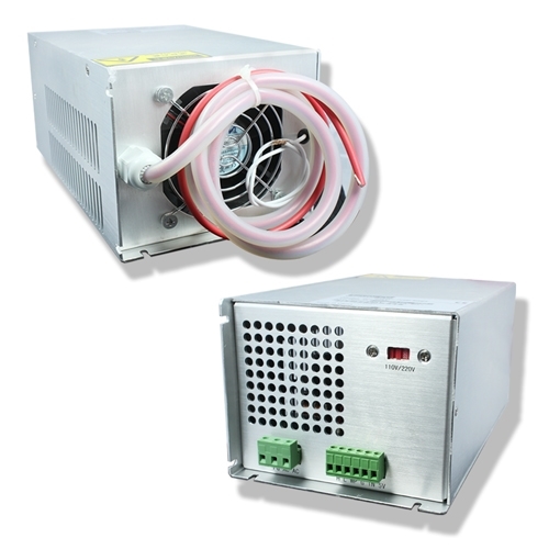
Fun thing is that since the tube was 45W, the power supply had to be their 40/60W one. What with that? Well, the 60W tube is just longer (1250mm instead of 1m) so, sometime in the future, I could just make a longer cover and change the tube…half a meter long cover, tough…that’s a bit of an overhang, ain’t it?

Anyhow, here are some more shots:

11865031_763947077067594_6361204293711766604_o

I was going to make the cover in metal, that’s the reason behind the squarish hole, but I didn’t had the bending press at hand, nor was going to buy one, yet. While I was shopping for supplies, I saw a PVC tube in the shop, and just ran with it (not literally, of course

11893979_763947073734261_6963808570223930740_o

7 screws for the 7 dwarf lords to hold the cover. I would have preferred a bit more margin in there, but the square deed was already done.

Lazer

Almost everything has sleeves, especially around power cabling.

20150903_234400

The laser in the workshop. Yes, I have lost a bit of table…but it will be worth.

I have some bits to wire up, but all the important parts are in place.

Next installment: Controls, wiring, cutting performance.