So, what you may not know is that I spent all of 2022, developing a joystick controller from scratch.
About two years ago, from the writing of this post, I began playing Star Citizen. I did have it since 2014, however, I was never able to play it due to lacking computer (4fps looking at the ground of the hangar doesn’t count as playing, does it?) and I truly forgot about it, until some life developements brought me a powerhouse computer that could actually run it.
Of course, I got hooked immediately, and began picking up hardware. A cheap joystick…then went HOSAS with a second cheap joystick. Also got a headtracker, for wich I promptly modified it’s headpiece…you know the jazz.
But of course, cheap joysticks always end up in the trash, so to speak. The ones I got, let’s say where not the greatest ever made (altough they did have a particular set of characteristics that I liked from a modding perspective). So, I started looking at what the joystick landscape was offering.
And, surprise!, I didn’t like what I saw, and the rest is forgotten history. (go read the fucking subreddit if you want to know more).
ANYWAY.
I always thought myself as a HOSAS (Hands on Stick And Dick…I mean, Stick), since HOTAS (Hands on Throttle And Stick) had a strong dissapeal to me.
However, after finishing the joystick and using it extensively, I found out I really didn’t felt the need for another joystick, but rather, I would prefer an actual throttle.
Those come in two flavors, lever and linear.
Lever, as you can see below, moves the handle in an arc, twisting your wrist in doing so. I am definitely NOT a fan of that system, but it’s certainly easy to sense.
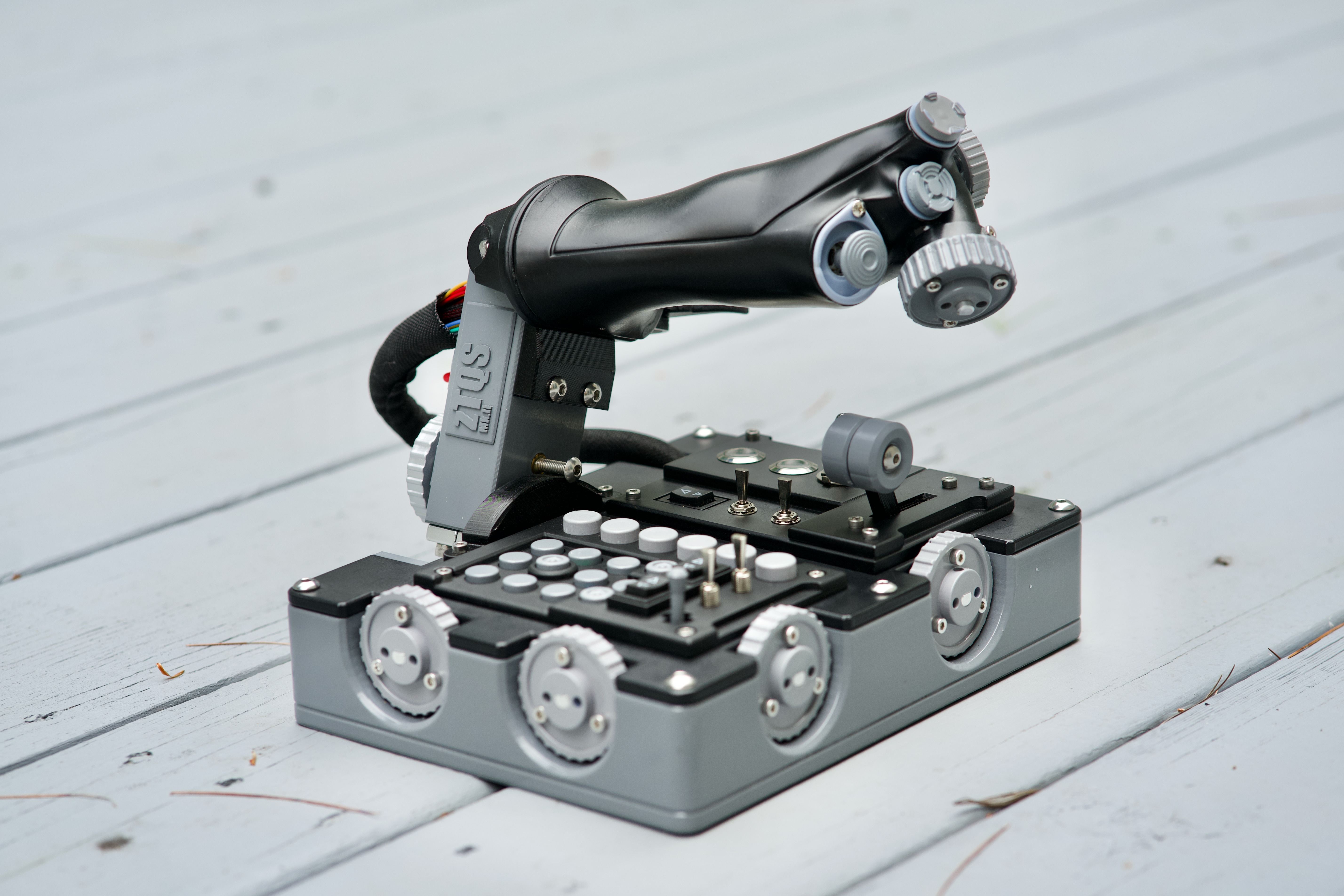
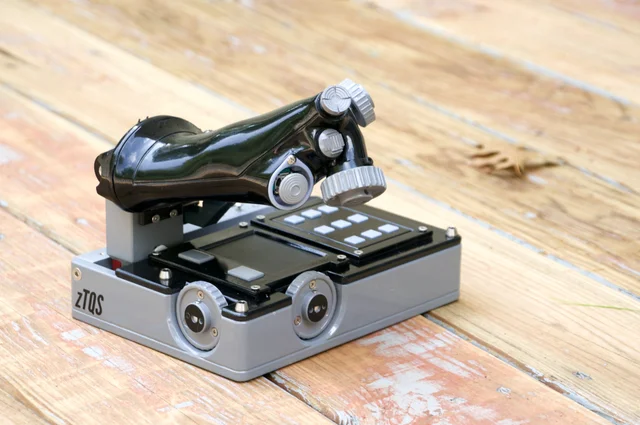
The linear type, as you should have already guessed, keeps your wrist and hand in the same position, and allows handle movement back and forth, wich also kinda feels more natural, but at the cost of greatly complicating your life when you want to know where the fuck the lever is.
So, of course, I ended up making my own (work in progress):
This throttle will have it’s own post when it’s ready (as will the joystick), but all this intro was required for you to understand the following bit.
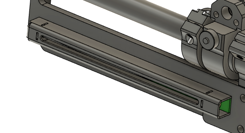
So, as mentioned, this has a forward movement of 100mm, but how the heck do you sense that? My requirements were:
1: Easy absolute sensing. No encoders, mouse sensors, or LVDT’s.
2: Contactless-ish (no resistive types, wich rules out general potentiometers).
3: Easy to source (DiY doesn’t count, as long as materials are not weird AF)
With that in mind, as much as I would have loved to use inductive sensors, they are not super easy to use OR design yet, so I ended up thinking about making it hall sensed.
HOWEVER
I could not find for the life of me, a 100mm long, 2x1mm neodimium magnet that I could use to directly sense all the lenght. In retrospective, I am absolutely glad I could not find such magnet, because that led me in a weird and wonderful design path:
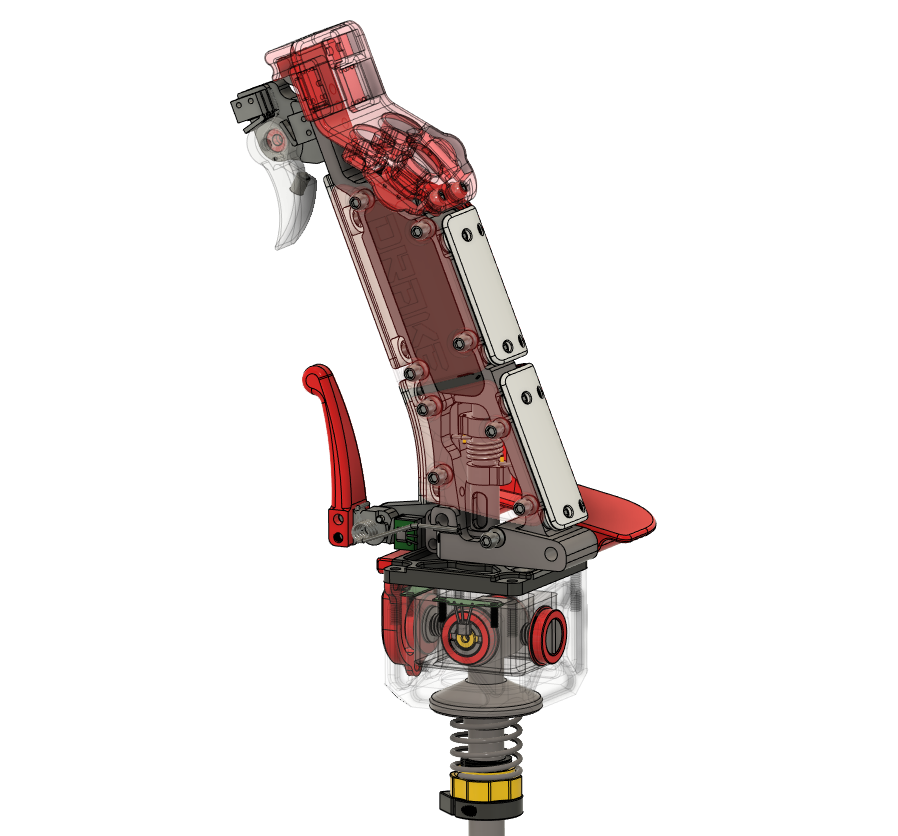
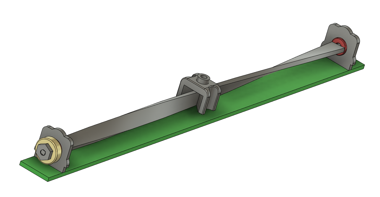
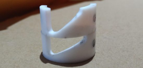
Wich ended up looking something like this:
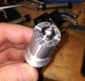
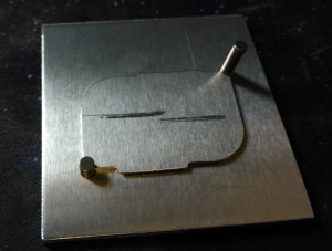
It is very simple, actually. A twisted bar is attached to a diametrally magnetised neodimium ring (wich is read by a hall sensor) and a slider that barely makes contact (with PTFE inserts), moves along the lenght of the twisted bar, rotating it as it slides, and, as long as you don’t twist the bar past 180º, it will be an absolute sensor of the lenght.
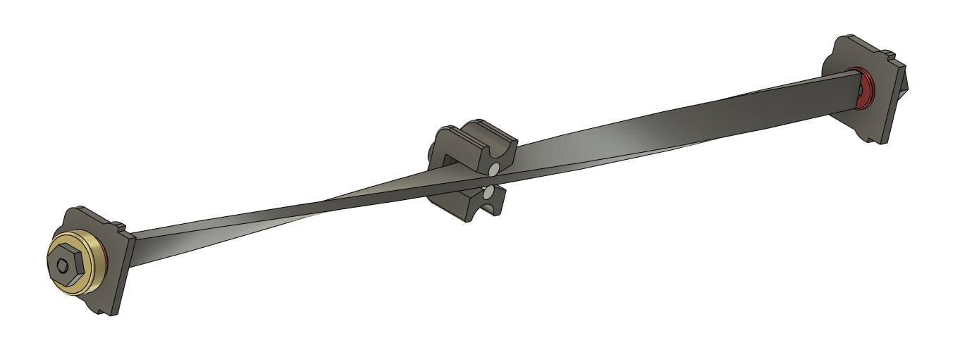
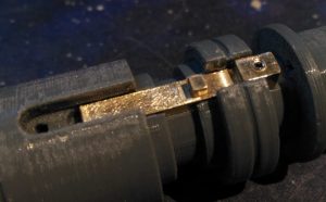
In the following image you can see a better view of the PTFE sliding surfaces over the twisted piece. The red blocks are not bushings, but actual miniature ball bearings (1.5x4x2mm, flanged)
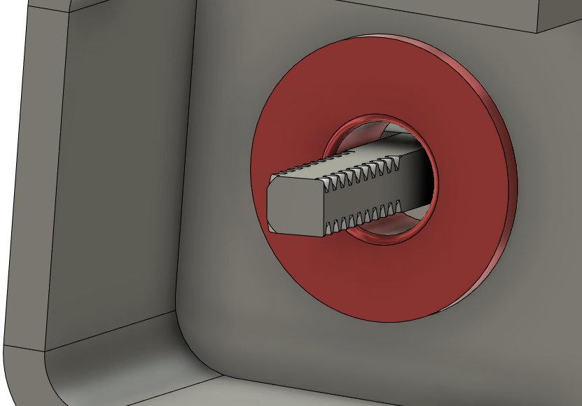
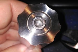
Attaching the twisted ribbon to the ends of the hall potentiometer, is made by threading the ends of the ribbon with an M1.4 nut, wich leaves a geometry like this (plenty strong for the aplication):
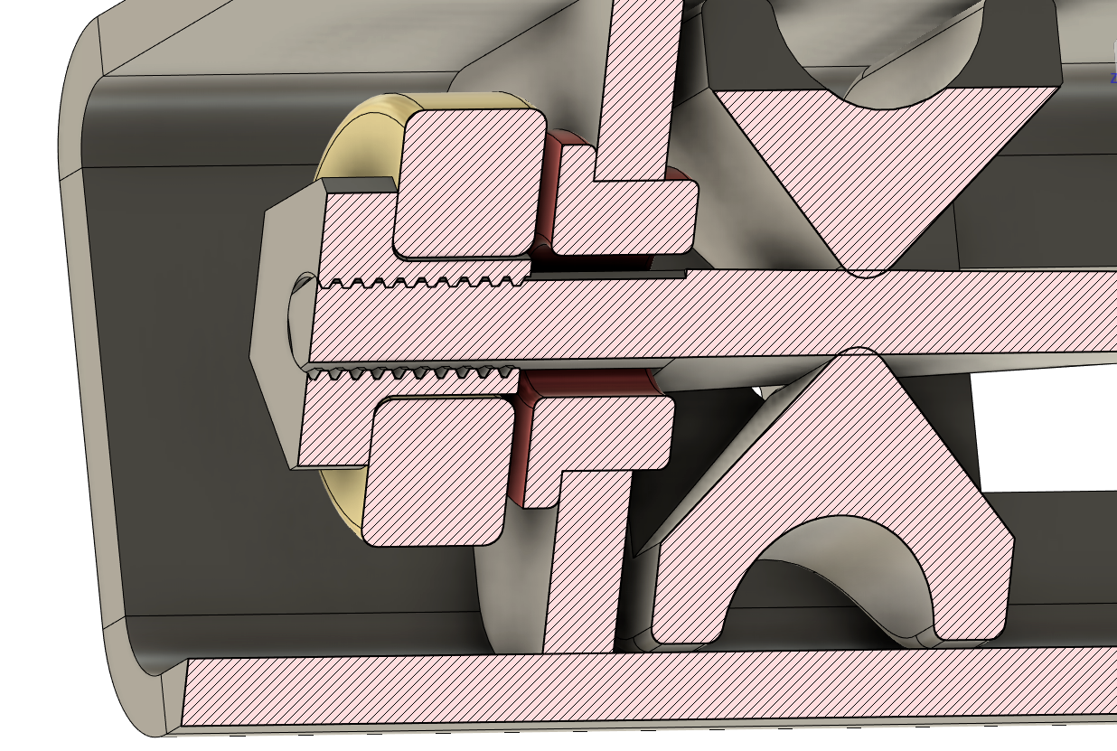
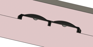
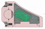
And a cross section of the assembly looks like this (missing a washer in between the bearing and magnet, I forgot to model it, and the slider is an older simplified version):
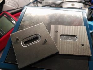
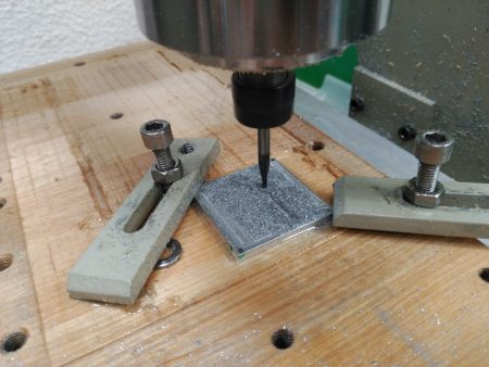
And now, it comes the moment of truth, can I actually build this shit? Keep in mind the hall linear potentiometer section measures 10x10mm (actually, 9.6×9.6mm*lenght) wich is not THAT dissimilar to other potentiometers in the same measurement region, wich means there is not that much space to fumble around.
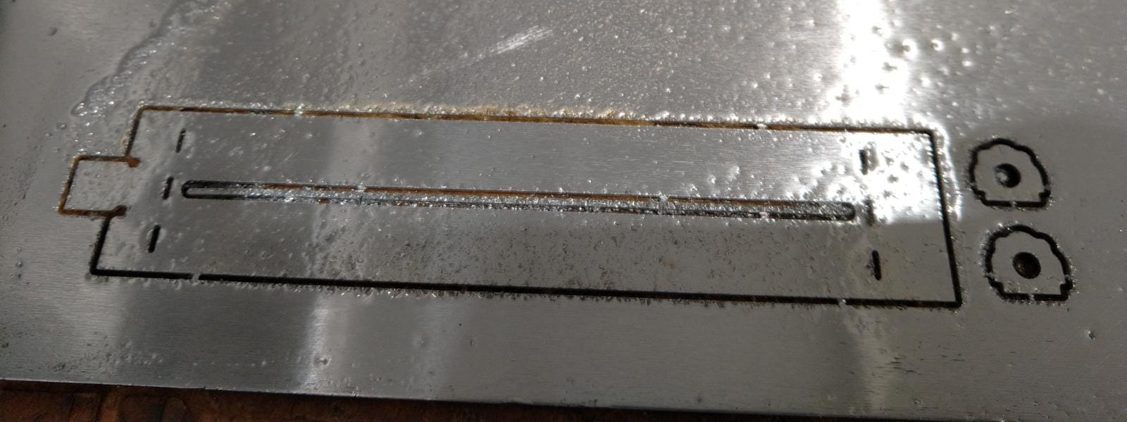
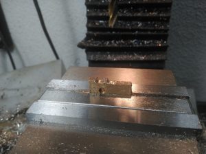
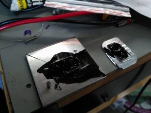
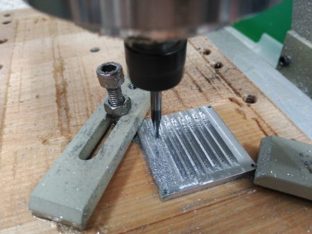
Well, it seems the 1mm endmill can do what I asked (milling 0.8mm aluminium sheet) laser cutting would be better but I don’t have access to one.
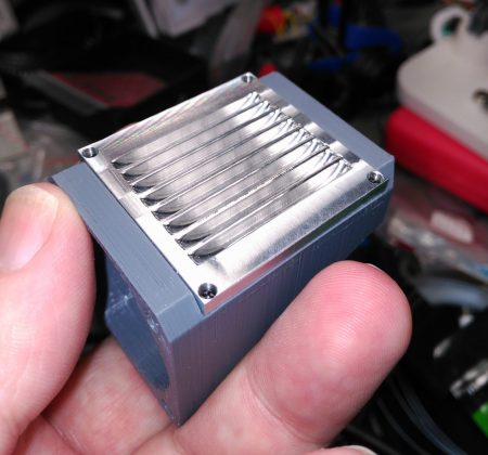
Postprocessed (background matt squares are 10mm per side). Twisting the ribbon can be acomplished with a pair of pliers (on aluminium).
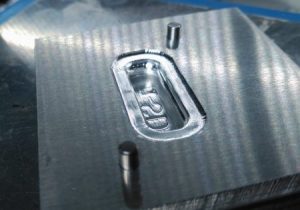
After some bending trickery (and a pair of utter fails), I did get an useable piece I could test:
And now I can do my own custom hall linear potentiometers without depending on anyone.
I haven’t written much lately, I know (and NOT sorry about it, tbh).
Let’s say life got in the way, however, I will start blogging more this year, wich seems to start well enough for me. Lots to write about, since I’ve been doing a lot of cool-to-me shit, you probably don’t care about.
So, I have been feling the need for some helping hands for a while, but I was not sure what I wanted. Before trying to reinvent the wheel, I went and looked at what was commercially avaliable, and I was kinda disappointed, to be honest.
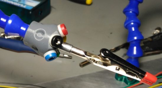
Barring some high end (and pricey) stuff, mostly what there was where either those cheapo magnifying glasses with a pair of alligator clips or…this:
I mean, they haven’t even bothered to change the end nozzles, just stuck the alligator clips directly…FFS
I was definitely NOT going to buy that, but given the budget constraints, I could not get much else…or could I? (y’all already know the blog, a post never ends well, does it? (well = purchasing something straight away)
In a happy coincidence, I remembered I had bought long, LONG ago, some flood cooling arms for my milling machines, but I never used them, they where too big, and I don’t have the mill in an enclosed space, so flood cooling is a no-no. So, I could use those for experiments at least.
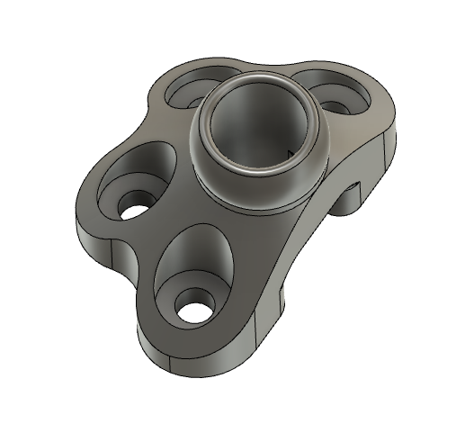
For starters I designed a base that I would screw onto a metal plate:
And why, you ask, does it have a cutout in the back? Well…you see, the flexyarms are hollow, so…I was thinking about routing cables through the arms themselves. It should make for a cleaner space just over whatever you where working on. Also, help with the issue that the cables can actually pull the board or whatever you are testing around, and maybe even short circuit something that they shouldn’t.
Bad example, but you get what I mean.
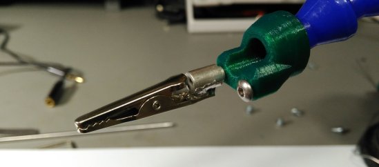
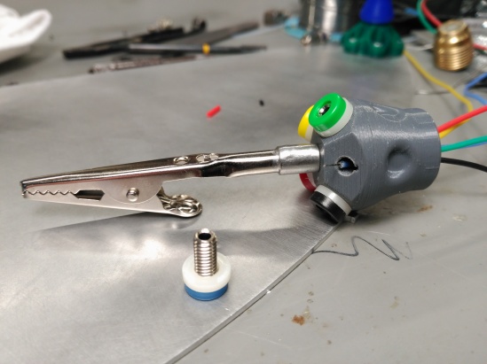
After some temptative designs on the alligator clip end
Y setled for a more unconventional solution: 5 radially spaced 2mm banana connectors around the clip:
With that decided, I mechanically wired the connctors to some silicone cable (28AWG because I didn’t have anything larger)
The small recess makes some space for the cable, that has been tinned, and the threading motion holds it in place very securely.
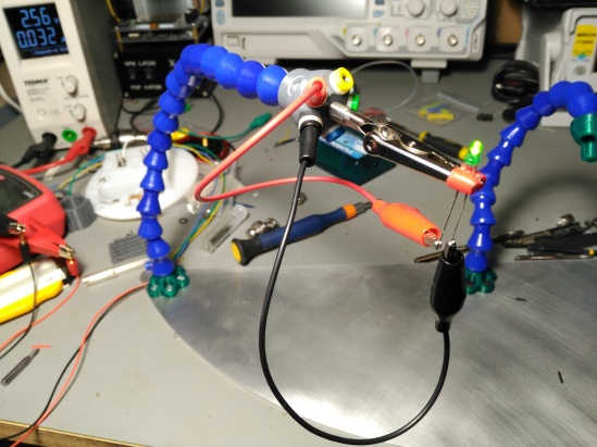
After the deed:
I had those two cables around, some shorter ones should be made later.
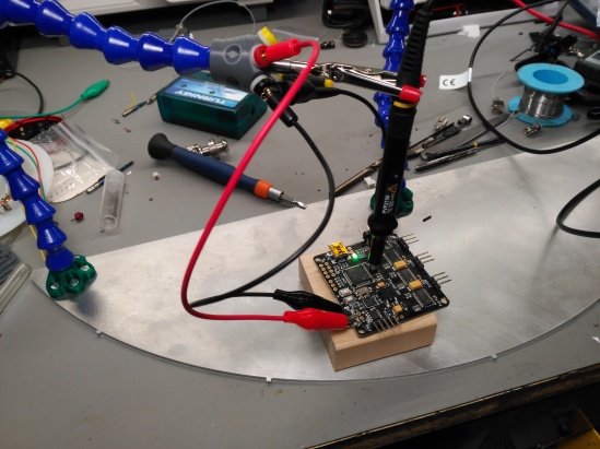
Experimenting with it:
And that’s it, just some weird-ass helping hands mod. XD
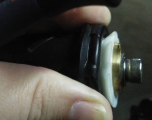
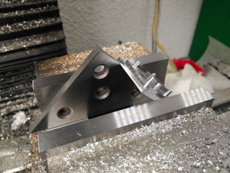
When we left last time, the only large bit missing where the metal brake shoes and extrernal sleeves. The latter, because I’m a fancy fuck, where to be machined out of titanium, because it would be easy to anodize later.
I have to confess I wasn’t particularly sure I could pull that off on the first try, with just a 100mm long stock of titanium that would have enough material for just the required pieces, but I braved myself and went at it.
Titanium is notoriously picky to work, especially without carbide. As smoothly as the first piece (lathe work) went, as bad the second was. I managed to harden a small section of titanium and destroyed 3 consecutive cobalt drills trying to plough through it. In the end, I could ram through the hardened part with an endmill, and it went well after that, but damn!, as I already told you, there where no second chances with the stock I had.
Second op in the mill was much more smooth, especially because the carbide inserts in the boring head:
Ye, that fixturing cost exactly 10 cents. XD
Unfortunately, on the lathe op I had made a slight mistake and forgot a spring pass, making one of the internal diameters 0,1mm larger than I wanted. It doesn’t seem like much, but it had a noticeable wobble in the test internal piece.
As luck would have it, also one of the counterweight bodies was 0.05mm larger in diameter, so I was able to just match the sleeves to the bodies and have a perfect fit. ¯\_(ツ)_/¯
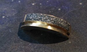
Also, while on the blueprints I had matched the final diameter of the sleeves to the original counterweights, I decided I preferred to have them slightly larger (+2mm in diameter) to enhance grip.
Second to last operation was to trim the sleeves to final lenght and mill the recess that would accept the titanium spring ring that would hold them in place. First, a mandrel was made and turned barely undersize, so with little expansion, it would retain the sleeves.
A bit crude, I know.
The operation was smooth as silk:
Test!
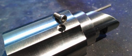
Last op was drilling and threading the screw in the left sleeve that would interface with the teflon ramp:
At first I was only going to use a grubscrew, but then I realized that without anything to actually torque it against, it would require loctite to stay in place. Here also came in handy that I had left the diameter of the sleeves 2mm larger, so I changed the plans on the fly and milled a small recess and turned down a M3 stainless screw head to it’s barely minimum to fit in there. I would still use a drop of loctite, but now I could use the softest one instead.
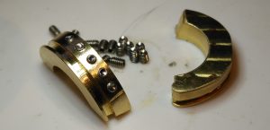
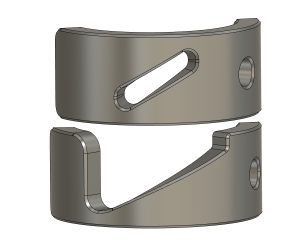
To machine the brake shoes I turned a holder groove in some bronze stock and let the CNC do it’s thing;
Cutting them down from the metal stock was an adventure in itself, but basically I clamped them on the vide with an internal separator, and milled away the whole bottom stock. Bit wasteful, but I can live with it.
So, it is at this moment, when finding out one of the assumptions you made is not quite exactly true…that your heart sinks.
You see, I had measured and calculated the grip zone in the throttle sleeve to be some lenght, but as it happens, that piece has some play, and instead of measuring the worst case scenario, I measured the best!
What does that mean? Well, where I had placed the o-ring that acted as brake, instead of being always like this:
Was mostly sitting like this:
I don’t even know how did it work on all the 3D printed trials, with the o-ring barely touching the nylon sleeve. Anyhow, I had to redesign the brake shoes, but after some tests, I saw that the o-ring was not particularly good at retaining either. If I used a softer rubber with more grip, it was also too soft and the throttle would just roll it around. If the rubber was harder enough to resist the forces, it just didn’t have enough grip to hold.
After much frustration, I decided to try less gentle means of braking, first, sandpaper:
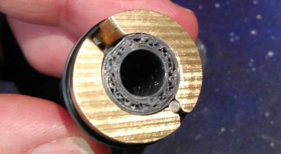
That worked, but even after switching to 100 grit, it still had this point where it would just sand (duh!) the surface and no longer grip. After much thinking, I concluded that I needed to actually grab the surface, but sandpaper was always going to have too much contact area, so I decided to use M2 grubscrews.
Used cup type until I received better single point ones.
You might have notticed that there are only grubscrews on one of the pieces, but not the other. This is because one of the brake shoes is working against the throttle spring, but the other would be working in favor of it. Thus, should the o-ring that keeps them closed, fail, one of the shoes would actually want to lock up harder, as the throttle spring pushed against it. The other shoe, instead, is forced away from the nylon sleeve, and only kept holding it by the combined grip from the grubscrews and the smooth shoe that reduces the slack between surfaces to zero.
It was at this time that I also changed the angle of the teflon ramp to a steeper one, to enhance the spring return of the left sleeve to zero (and also by chance, reduce the twist angle required to operate, making it more comfortable to use):
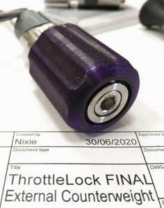
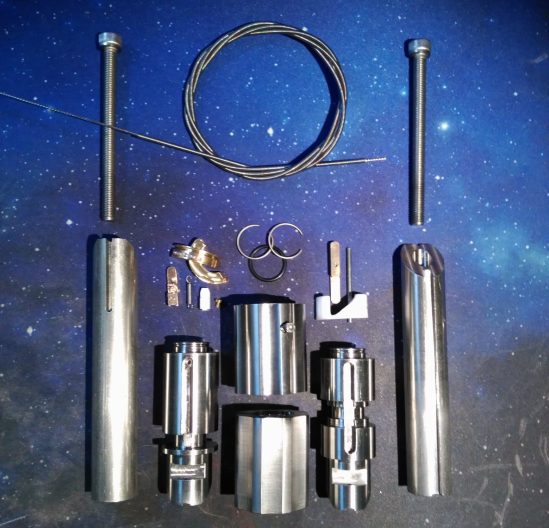
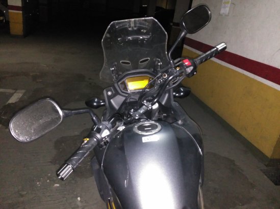
With that extra feature, all the pieces where ready to install:
I had start to polish one of the sleeves in this photo, but not the other, XD
A closeup of the mechanisms, just missing the bowden and steel cable:
But, does it work?
HELL YE IT DOES!
In the video I was using the old teflon ramp, hence the large twist angle in the left hand. Also, just general awkwardness of a new device you are not used to. Since then I have made it more natural to use.
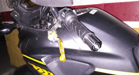
Beauty shots:
Conclusions:
Was all this effort worth it?
ABSOLUTELY. Now I can let go of the throttle to rest my right hand, or, especially, to check my right leg bag. I can’t get back to NOT having it installed now.
Is it safe?
Unlike ALL throttle locks, this is redundantly safe, as it does not lock, but HOLD. For starters, if you are not operating it, it won’t do a thing. If the steel cable breaks, it does nothing. If the return spring breaks, the spring-oring can close the brake pads by itself. If the o-ring breaks, the geometry of the gubscrew-brake makes it NOT want to lock the throttle (would actually try to prevent you from accelerating). The throttle holding can be overcome in any of the situations.
If, compared to ALL other throttle locks, those are not good enough arguments for you, hey, just go fuck yourself elsewhere.
Is it commercially viable?
NOPE. Altough the device is not especially complicated, and could be simplified here and there to make it somewhat cheaper, I don’t have the resources to do that. It would have to be made one by one, and noone has that kind of money to spend on this, nor I the interest to do it anyways (unless someone has really deep pockets and wants to change my mind).
Is it legal to use?
DEPENDS. This is safer by design than ALL other throttle locks in the market, but if those are illegal in your country or state, this will still be. With that said, it is absolutely invisible to any visual inspection, no matter how thorough, as changing handlebar counterweights is perfectly legal everywhere and there are infinite models. These ones just happen to be inconspicuously loaded.
What did you expect, a door? Do I look like Hodor to you??
Continuing with the adventure, I proceeded to mechanize the smöl piece that pulls the cable. The best spare metal I had around to do it was a small block of bronze, so I just went with it.
Drilling 1mm holes, even in easier material like this, is always unnerving:
Yeah, the M2 screw looks like it will hold properly.
In place:
Yeah, this photo was taken before the one on top of it, before rounding the peg.
Another issue I found was that the original inclined plane I had made seemed a bit too steep for the mechanism. At the time I was afraid that a shallower angle would result in the spring not being able to pull against the resistance of the rotary mechanism. After pondering a bit, I decided to make a less steep path, and also optimize the piece a bit, since this mechanism is only pull, and won’t require push of the slider:
And here, working absolutely beautifully:
The only momentary setback is that I only have at hand 0.6mm steel rope, but the PTFE sleeve is 1mm ID. That can introduce a huge amount of backlash that’s difficult to compensate, as you can see in the following video. Once I block the plunger of the brakes, the sleeve starts moving on it’s own to absorb the extra slack:
I did find a short piece of 0.8mm rope, and indeed works much better.
Unusual are the cases where a standalone IP68 button can be installed in a very compact electronic device. Even if the Nixie-CAM (NC from now on) is for personal use and I could just get away with having to unscrew things and a little bit of impracticality regarding storage and actuation, I kinda preferred, to make it look store-bought. Any product that has removable pieces or accesses, is usually accompanied with some sort of soft cover or rubber button pad. Of course you can create an o-ring sealed shaft to actuate an internal tact switch, but that’s rarely practical and comes with it’s own problems.
And that’s the ulterior motive for experimenting with PVC ink, as mentioned previously. Definitely was not for keychains XD.
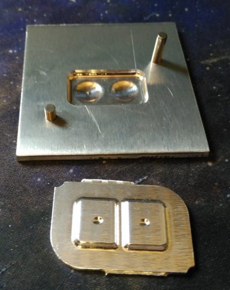
Picking up the 3D models for the μSD cover and buttons, I built a pair of 3D moulds around them to be machined out of aluminium.
They would also be the first time I would be doing parts that needed locating pins between them. Not that it’s complicated, but first times are always scary (AND the fact that I had no spare stock for the pieces didn’t help easing my mind. XD)
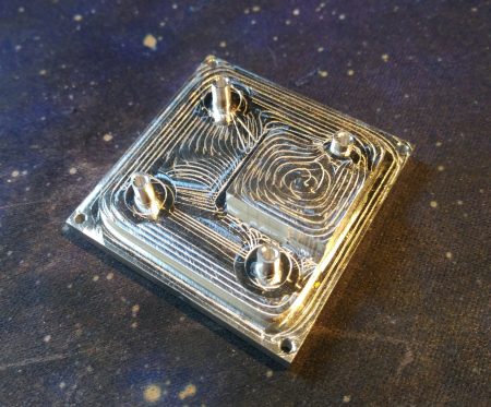
First I did the buttons. Having seen that a ball endmill would push material rather than snagg it on the first keychain test (where I missmeasured the thickness of the stock), I was somewhat confident I would get away with pushing my luck with aluminium deformation for the domes, wich measured 2.98mm in 3mm stock . If you look closely, one of the domes tops is a bit wrinkly, but for an experiment, that was good enough.
Since the pushbutton recess male part had to protrude from the top mold, I decided to simply cut much more area than needed and then cut around (crossing the pin locations so it would still align)
Liberally apply plastisol grease:
Press:
And apply 150ºC for 90 seconds at least (you can apply more time if needed), then enjoy the results. Note how the central rib prevents the left button from moving when depressing the right one.
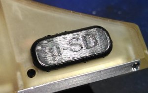
Next, the mould for the uSD card cover. I made a slight change between the original and the test, because I had not yet received the 0,2mm engraving bits (In case you nottice the difference between the original 3D model and the final piece.
The recess in the top half was so the final thickness of the piece would not interfere with the internals had I made it all the way stock thick.
Assembled. At least this time I didn’t forgot to invert the text so it would read properly ^^U
By the time I had made this, I had PVC ink solvent, with wich I thought I could make the rubber a lot more liquid without changing properties too much, but unfortunately that was not the case, and for the PVC ink to be liquid, it has to be specially formulated. In any case, using a syringe and some vacuum, all the molds should be easily fillable with the material I already have.
I kinda forgot to set up the stepover at 0,05mm, so you can see the individual passes of the ball endmill. The letters look fine because I did a special engraving pass, not just relying on just the horizontal passes.
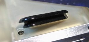
I did remember to do it for the top half, and the results show as a very smooth surface that will seal properly against the case (it’s made to have an interference fit, so it’s always snug)
Live:
With that taken care of, next step was to put the pcb buttons in place. However, at this point, I just discovered that the video board ALSO had a power shutoff circuit included, wich had rendered the circuitry in the pcb unnecesary. I also had mismeasured the board thickness and got a 1.6mm, wich didn’t leave much height to actually glue the rubber buttons…
NOT that that was going to deter me, tho!
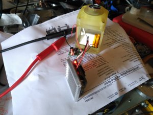
I just soldered the REC/STOP button cables and attached those to the internal pushbutton, so they would have a better grip than just soldering on pads alone. After that, I attached all the circuits and batteries, and did a small 24 minutes recording test to see if anything exploded:
Luckily, nothing did, but I noted that the converter board did get hot, as did the main heatsink. With that in mind I assembled the camera to see if there would be space to add a small aluminium board to help dissipate the heat from the converter into a larger area (and in the process protect the li-po battery from focalized intense heat).
Yeah, I definitely could fit something in there. (yes, I was very careful about using steel tweezers around powered electronics).
Some hacksaw time and a bit of vice bending later (without the bend the video board AND cables would not fit):
And…it was about time to close the thing!
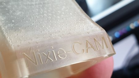
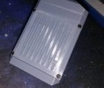
The translucent body of the camera will definitely NOT allow for covert recording:
I won’t cover the magnetic connection in the back of the camera because it’s exactly the same than the F9 I did before.
And with that…the V1.0 of the camera is finished!
Testing.
Since I lack a proper thermometer (or FLIR camera) I decided not to risk yet a full zero airflow thermal test before I can get at least some footage recorded (nothing would infuriate me more than just not being able to test the camera in the helmet).Remember I did a 24 minute test but all the pieces where outside the enclosed camera space, so that was just a best case scenario on dissipative cooling.
What I did have to do however, was a full test with at least a bit of air (in the end this is a motorbike helmet camera, it will have airflow over it most of the time anyways. It just was not very scientific due to the lack of instrumentation.
I picked up my vertical home fan and put the camera to record the highest airflow setting for 1h straight. after such time, the heatsink was hot to touch, but I could rest my hand on it indefinitely, so I reduced the airflow to the setting number 2 for another half an hour, with more or less the same skin-test result. I further reduced the airflow to 1 and left the camera for another half an hour (for a total of 2h of continuous recording) and by that point, the heatsink was too hot to continuous touch, BUT not insta-burn your skin.
Note: Ambient temp was 27-28ºC
After this, I thought about seeing how the drone world heatsinked the main processor, only to shockingly discover they just don’t…
I agree that a drone in flight will get some airflow, but at the same time, they sandwich the video card with other controller and video transmitter boards, so it’s not like it has the best cooling situation…
So any heatsinking is definitely better than no heatsinking I would say.
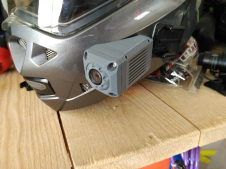
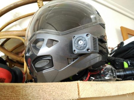
By the time I was writing this post, I didn’t have proper double sided 3M foam tape, so I just attached the camera with random tape to have a glance at how it finally fit:
Yeah, I agree the piss colored body doesn’t help much, but I’ll take care of that later.
I haven’t removed the old mount yet, but that I’ll do as soon as I get the proper mounting foam for the camera.
Definitely not switching to a GoPro now…
Nope…
The best thing is that, within reason, I don’t have to worry anymore about the camera orientation, I can just tilt and twist the gimball to the proper position.
Smol test at the balcony. Color looks a bit saturated, maybe I can change some firmware for that, but then again, this is desert-like sun, so…
Performance.
Daylight:
After testing, this camera performs slightly better than a Sena Prism Tube, wich would be a direct competitor of sorts.
Light management is better, not being overwhelmed by bright lights as much as the sena. As soon as the bright spot occupies enough part of the field of vision, the Nixie-CAM (CADDX Turtle V2) starts compensating, instead of waiting longer for a very sharp change in light.
(sound warning!)
I must say, even at 1080p/60fps on youtube, the original video looks better.
Night time:
1.- City Led Lights:
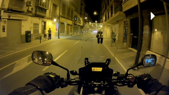
2.- Sodium Vapour street lights:
3.- Entering a less illuminated city road:
4.- Roadside pole lights only:
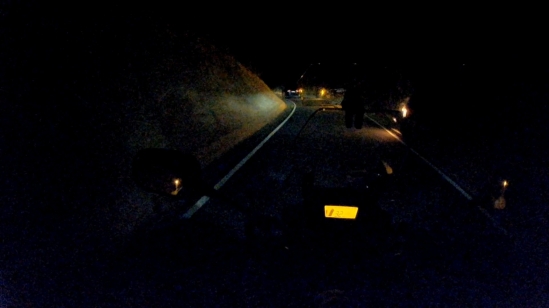
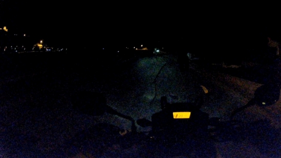
5.- Absolute darkness (No road lighting, LOW beams):
6.- Absolute darkness (No road lighting, HIGH beams):
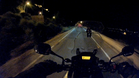
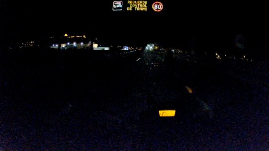
7.- Non illuminated highway, no other cars:
8.- Non illuminated highway, being overtaken by a car:
Analysis:
Pros:
Infinitely better than a 20$ F9 tube camera.
About 2/3rds the price of a Sena Prism Tube, with slightly better performance on mine.
Much more streamlined than any other existing cameras at price range.
“Infinite” battery capacity until max record time (minimum should be 4.5h at 1080p/60fps to 64Gb, but storage usage varies wildly so it’s hard to calculate. μSD cards are cheap tho.
My fucking own design.
Cons:
Heat management is difficult. The camera requires good airflow, but I’m not sure final operating temperature WITH the heatsink will kill the board, I’ll be testing that soon.
Piss color body (hey, it was cheap…).
If you want to count it, not being removable from the helmet (but that’s how I want it, so…)
Sound at speed is awful? (maybe can be fixed in post, maybe something can be done about the mic)
Veredict:
Was this worth it? ABSOLUTELY!
So much in fact, I’ll start working on a V1.5 camera to make it even better. Of course this is not a Go-Pro or any other generic action camera and it will never be. This is an extremely specific motorbike helmet camera that works (and relies) on riding conditions.
See ya!
P.S. Want one? Yeah, I’ll build one for you for 400€. Fucking expensive? Do you expect me to work for free or what…
Recently I finally uncovered what material is used to do this:
Because yes, it says “PVC” in the label, but what is the liquid they use? Well, as it happens, it’s called (doh!) “PVC ink”, and one of the most avaliable commercial names is PLASTISOL. It is used in the shirt printing industry around the world, so it should be fairly easy to find locally wherever you are.
I know, silicone rubber can be used for that purpose, but it has shelf life and any leftover mix will be lost if not used, whereas the heat curing (150ºC/90secs – 170ºC/30secs, special aditives to reduce temp to 130ºC exist) material will just stay as it is, and any non-contaminated excess can be just dipped back into the container for future use.
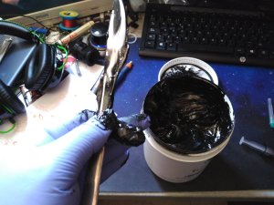
When I first uncovered the material name, I was not sure it was the right one, so instead of bitting the bullet, as emotion would want, I just bought a 1Kg black can to test for about 23€ shipped.
Damn that’s messy…
To properly mix the ink the first time I used a knife, but that was far from ideal. I knew I wanted a different tool for the job. Something called a cream spatula (had to learn that from Twitter, I only knew the shape until that point):
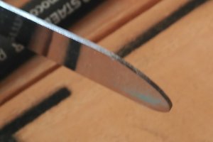
The thing is, I bought the cheapest one I could find, but upon further inspection at home, the edges where really bad, very coarse and dirty:
I knew I didn’t want any edges to rub and cut the inside of the plastic plastisol container, so I quickly went to town with the scotch brite pads to smooth that out. The result was good with a lot less effort than I had anticipated:
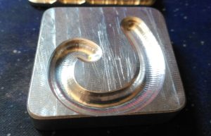
As a test piece, I would use this CNC test I did years ago. A nice curved shape on an aluminium block:
And my trusty hotplate. It does not have a huge amount of heat capacity, so the temp can drop once putting a big enough mold, but for the small things I usually do, this should be more than enough. Remember this stuff curing temp is between 150ºC/90secs and 170ºC/30secs, but it won’t fully harden until you cool it. That means that poking it to see if it cured while still at high temp, will not give you an adequate answer. Don’t worry though, it’s easy to get the knack of it, you just have to totally avoid it smoking (closer to 170ºC), because, like with all burnt plastics, the smoke is highly toxic.
An important detail is that you can also gel the ink at about 50/60ºC so it doesn’t run around, but still adhere to any other inks you put on top later, very useful to do double sided things, for example.
As always, since you are reading this, you know it worked. Shame, there’s no way to surprise you anymore…
So, next try was doing a mold on purpose, and I settled for a keychain-esque piece:
But the thing is, I hadn’t touched my CNC in a fucking long time (maybe…about 1.5years…yeah, too much time) and I kinda made rookie mistakes all the way on the first test. For srtarters, I assumed the stock thickness, but I was wrong, instead of 4mm it was 3.
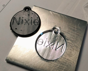
And I also forgot that the piece would be mirrored…and forgot to mirror the mould instead:
Nothing some phohoshop can’t fix:
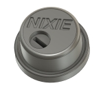
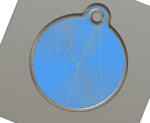
Joking apart, this material has sooooo many uses I don’t know where to begin, but in the meantime, I decided I wanted to do a nice keychain to sell. After a meh poll on twitter, I finally settled on a Nixie tube…because you know, if you do something, do something cool, right?
After fiddling a bit, I arrived at the following design, kinda okay, but of course, totally missing the grid:
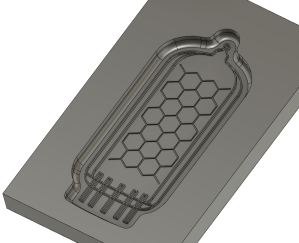
Much deliberation later, I decided I would add the grid to the main mold, and sort the addition of the number in between steps, to get something like this (grid not to final size, that’s just a test):
So, how would a mold for that look like?
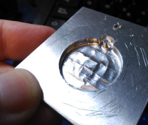
At this point I didn’t have any 0,1mm engraving bits, but decided to do a test anyways, because you know, cool molds and experiments, and I sorta could not wait to see something other than a crappy inverted text keychain.
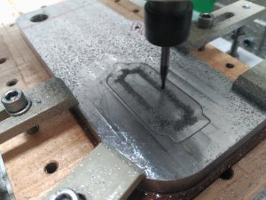
This took a while…
The 2mm ball endmill could not reach the smallest details, I was fully aware of that, but this was a test of the capabilities of the 3020 cnc anyways. I might also have overreached with the heat capacity of the hotplate, but it worked in the end, it just took a while longer to reach temp.
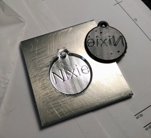
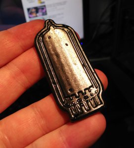
And…this came out. The cad program didn’t pick up the fine detail of the grid with such a big endmill, wich is a shame, but nevertheless the wall finish was quite acceptable.
It’s definitely not perfect, BUT, it’s a promising start. I’ll get rid of the bubbles by using a more liquid plastisol, and once I have the fine cutters, I should be able to reach many more details. Buying all the colors I need for it, is a different matter, though. ^^U
Anyways, the keychain thingy is just an excuse to play with the technology. My own ulterior motives will be seen later on.
When we left last time, all I had was a fdm 3D printed body and not much else. Much work had to be done still, so this is what has happened since.
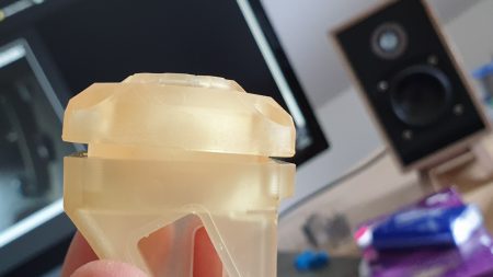
My The body is ready:
I asked a favor to get the camera printed in STL resin. To be able to aford it, I had to accept the piss colored resin avaliable, so the camera won’t look fancy yet, but hey, at least I could afford it:
So sharp!
You can see the camera lens sealing ring.
A bit of postprocessing will be required to mate the pieces seamlessly (quirks about resin printing, but it will also help with sealing after everything has been fitted properly, so I’m not gonna complaint)
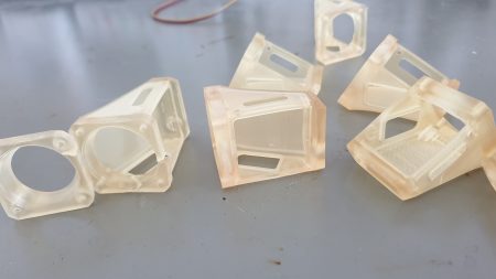
Not everything was easy, apparently the bodies where a bit fiddly to get out of the printer and got a few damaged ones before having succesful prints:
Anyways, got bodies! /hides the digging supplies/
Next question, please. XD
Power Button & Switch:
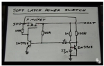
As mentioned before, after looking hard for a IP68 micro power switch and not finding anything that had the price of a small car with a kidney on the side, I had to capitulate and go full electronics with the approach, using a soft power button.
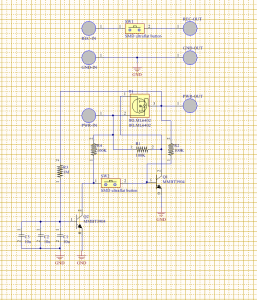
I found this circuit on eeVblog:
And proceeded to build a PCB around it. Said board had definite dimensions at 24x14mm (r3 corners) but I should be able to fit such a simple circuit easily (hah!), so, it was Altium time!
Funnily, I kinda assumed I would be able to quickly fit easy to solder 1206 components when I was selecting size:
Ooops…not sure anymore…
But somehow I managed to put everything perfectly:
So perfectly in fact, that I didn’t even have to put tracks for the switches, just direct vias (to be capped off when the component is soldered, so the whole pcb is hermetic in the body)
I know someone will be triggered by the 90º difference between switches. Enjoy! XD
Ordered them from OshPark in after-dark, just for kicks. XD
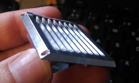
Heatsink that shit:
First time I powered the camera, I notticed that the whole board was noticeably hot, and the main processor, even more so. I imagine that’s not a problem ina FPV drone flying at 80+ kph, but for a closed body camera, that heat can’t be allowed to accumulate.
I mentioned before the sideplate that would have the main pcb attached neeeded to be made out of aluminium, easier said than thone, ^^U
Just about before milling it, I made a few modifications. I added the studs to hold the pcb, instead of having to add them later and thread in the thin baseplate. That would give me more thread lenght for the screws AND allow me to make the fins 1mm deeper, because the interference between them and the M2 threaded holes was eliminated.
But one thing is making a nice design, and another is to actually build it. That piece could be definitely made with manual milling and some filing, but my trusty 3020 can more or less do aluminium if you are patient enough, so I went with that instead.
Fusion definitely made some pretty swirly cutting patterns that I decided to save, even if that is only going to be seen by me. When cutting the piece, I kinda overreached the speed at wich the router was moving (the motor was fine, the cutting sounds where great) but at some very sharp changes, it definitely flexed enough to make the rounded corners a bit wonky. The studs also suffered from that speed excess, being a bit overcut on some sides. I definitely need to make a new piece someday that doesn’t have those mistakes, BUT, the piece was mechanically and geometrically functional, so I still went with it.
Also, this was my first piece with a double sided operation, wich made me nervous (the first milling was about 3h) but I was feeling confident, and as long as I didn’t switch off the router (or the power didn’t go out) I should be able to mantain the coordinates to process the piece.
First I drilled a very tight pocket where the small square of the plate would fit (had to hammer it a bit, wich is good in this case).
Given the experience with the other side, this time I went very conservatively on the feed, maybe even a bit too much, as the whole piece took a bit over 4h to be milled.
At least the results where really excellent (for the machine) The screw holes where 1.5mm but the heads where 2.5, so, with my newly gained confidence, I made a post program to itnerpolate those from a 2mm endmill. In the model I had made the screw seats about 0.4mm thick, but in the real aluminium piece, even if it’s more resistant, I left it at 0.8mm (remember that for later).
Gorgeous!
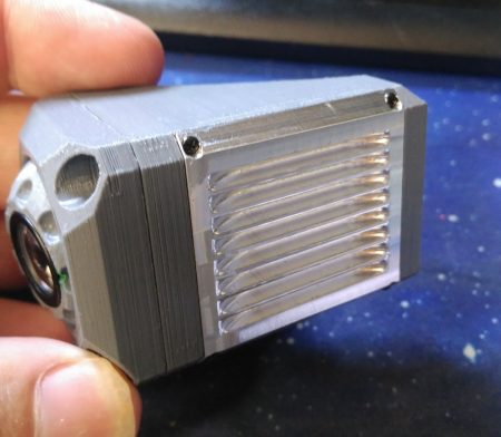
I didn’t want to spend more time in the router, so I decided to do the big chamfers in the milling machine, with probably not the best setup for the angle:
In retrospective, I could have done a few things better, like attaching a thick parallel to the side of the triangle to have more resting surface to set the plate, for example, but well, that’s for the next time, I guess. (definitely will be making more than one camera in the future)
Anyways, I did the cuts, and altough I did not make them perfectly simmetrical, at least I did not mess up badly, and you will not nottice once it’s mounted:
Camera beauty shots:
Remember what I said about the screw base thickness being left slightly thicker? if you look closely, you can see, the heads protrude a sliiiiiiiiiightly bit to the side of the chamfer. It’s not functionally a problem, but I know, and you know, and I will definitely change that for a future version, putting them a bit more inwards.
In any case, It’s friggin cool, isn’t it? (It’s my blog, I can say whatever the fuck I want, tbh)
I’m missing the PCB and it’s components. The bodies still have to arrive from Germany, and some o-rings, a micro Li-Po and the power board from china too, so the camera it’s not really near completion yet, but it’s close.
A few days after poking around with my F9 camera and finding out there are no new or old firmwares avaliable, nor adjustments for the camera (or anything, for that matter) I decided to start again an old project of mine:
Building a helmet cam from “scratch”
Not from literal scratch tho. Drone camera tech is so advanced that it’s dumb spending time also developing the recording hardware with the enormous amount of options. Not that just developing the casing is easy, but also, what exactly do I want to achieve that no action camera in the market does already?
SO, WHY?
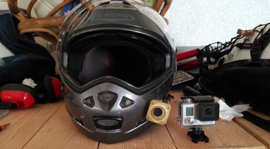
You see, I’m a fashion victim, I admit it. Every time I see a GoPro in a helmet, I get sick.
When I see this:
I think of this:
I know, I know, It’s not like there are lots of types out there. It’s either:
Tube Camera: Sena Tube / Contour HD / S20W / Cheapo F9.
Front facing Action cam: Ghost Drift / Stupid Sena 10C
Not gonna count the mohawk type cameras, albeit cool, because:
Cost: 500€ and upwards to orbit.
Bad helmet compatibility: Top vents, modular helmets and top solar shield sliders pose a problem with those.
And don’t get me started on the mounting solutions. They’re all so large, sometimes as big as the camera you want to mount. And the thing is, our helmets are curved, but none of the avaliable cameras use that to it’s advantage to make them more streamlined, and I’m thinking, why noone makes a wedge shaped camera so it has a lower profile?…
Well, if noone is going to manufacture that, fuck it, I’m gonna build it myself!
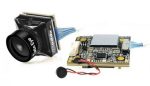
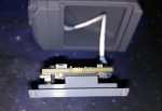
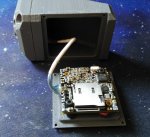
First I took out the camera module I had bought some time ago: a CADDX Turtle V2, real 1080p / 60fps (much better than the F9 camera) and just looked at it while brainstorming.
One of the main thoughts I had was:
“If I was ready to carry a powerbank and a cable for the F9 camera, why not remove the whole battery thing altogheter from the camera? (not totally true, but more on that later).
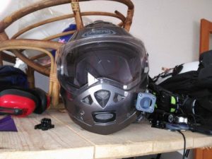
So, I got to work. First I made a simple suport to put all the parts near the helmet so I could visualize what I was dealing with. Be afraid NOT!(yet) this has nothing to do with how I wanted it to look.
With everything in perspective, the first thing I understood is that I wanted the camera to be gimballed, so I could fine tune the angle it pointed out, so, even if the body was not perfectly aligned, the POV would be adjustable.
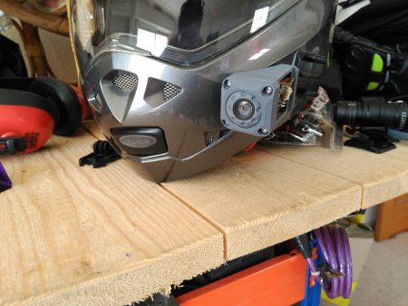
Implemented:
Frankly it looks more like a ready-to-burst eye, than anything.
With that, I started to devise what kind of shape I wanted it to have, I had very clear in my mind that the camera was to hug the helmet as much as possible. A limiting factor is the control board that measures 29x29mm (the camera body is 19x19mm) so the body itself MUST at least be a bit taller than 30mm. What I definitely didn’t want was the GoPro attachment, so that’s the first thing I removed:
In the helmet:
And compared against the F9.
Looking good, but I had definitely gone overboard with the simplification and volume reduction, and the pcb barely fit, plus the main processor requires heatsinking, so it was not like I could just make a plastic case and call it quits. I would have to add some kind of flat surface where I could embed an aluminium block of sorts.
After thinking about it, and some rough modifications later, I got this:
Much better. But that was built over many modifications over the same base design, making the whole Fusion360 file a mess I really didn’t want to work on. Thus, I started from scratch on a new file with more close to real measurements AND most importantly, a clear view of the shape the camera was going to have.
By advancing the gimbal ball (gimball from now on) holder front face, it was possible to make it look less like a sore eye and more like…well, definitely NOT a sore eye! After some more refining work:
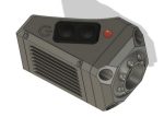
And adding the micro-SD acces port and status light:
That was looking great, altough the camera had started to get bulky at 37x37mm frontal size, and I got worried that the thing was NOT going to be as dramatic as I had hoped. So, I decided to print a simplified body and front cover to fact-check. When you see the first impression, well…it is indeed a bit bulky, altought compared with the F9, it does poke less from the helmet side:
But ah!
When you see it from the side, everything changes! Now the F9 looks humongous against the Nixie-Cam (“official” name, btw):
And without the F9, looks much better:
I went ahead and printed the gim-ball:
Beauty!
Gimbal working:
I literally checked the GoproSession size while writing the post, and it’s 1mm larger on each side!
After that I went ahead and printed the lateral cover. This piece must be made out of aluminium as it will act as heatsink for the main board, there is no way around it.
The protusion is about the size of the main processor, and the four screws will attach it securely in place. It also serves as port to access inside and make repairs easier than through the camera-ball hole.
In place using some micro-screws I had lying around:
But, what about the element exposure? No worries. The ball and lateral cover have o-rings, plus the silicone seal on the micro-SD card.
At the very least, the camera should be IP55 rated (dust and water splash resistance) but I bet it will be good up to IP68 (impervious to dust and very heavy rain, BUT NOT underwater-waterproof). This also brings the issue of the controls. This thing would need at least two buttons, ON/OFF and REC/STOP.
The main board has a pushbutton that starts and stops recording, but accessing that as a button from the outside would be a good alignment challenge, so I knew I wanted a separate button for that. For power control, I’d need a switch too, but as much as I looked around, there was no way of finding a momentary and a 2 position waterproof buttons that where absolutely microscopic (so to speak). Smallest I could find was 8mm in diameter and 15mm deep, wich would mess the distribution inside the camera, and waste precious space. After deliberating for a while, I reached the conclusion that the best option for all that was to seal an opening with a PCB that would act on one side as two buttons (with a rubber cover) and on the inside, as circuit board with a FET latching switch (and two normal connections for the recording button).
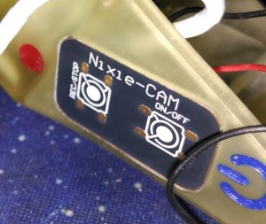
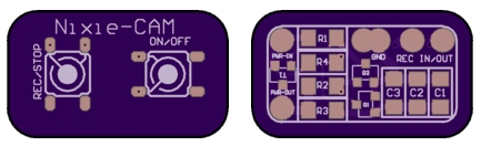
The outside, with comprehensible, yet unnecesary operating symbols (the buttons will be operated with the thumb, and facing down, so you can’t really see them. I made it this way because the thing you will operate the most is the SD card, and you definitely don’t want that to fall out, hence it being on top).
And on the inside:
The board size is 24x14mm(corners r3), and the inside area is 11x21mm(corners r2). The plan is to have the vias sit on the pads so after soldering the pushbuttons no hole is left and the board can be simply perimeter sealed to the camera body, ensuring it being waterproof. The board will also probably be conformally coated to prevent corrosion.
This will be the latching circuit, got it from EeVblog. I still have to select the particular components, but this should not be too difficult.
And now, some prototype beauty shots, because I can:
Some more details:
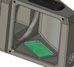
While making sure I had not forgotten anything important in the camera body files, I realized I had no reference point for aligning the gimball to be horizontal, nor a seal around the camera lens (I was kinda going to glue the camera to the ball with sealant, and be done with it, but that’s a bad idea).
So, I added a pair of horizon marks in the gimball front AND a sealing ring groove:
The camera will be held in place with tight foam and a very tight fitting o-ring, but an impact on the lens (wich do NOT protrude from the ball, so it would require to be a very direct hit) will send it inwards, protecting if from a possible lens break. Just dissasemble and pop out if nothing broke.
POWER
Remember what I mentioned before that this thing being batteryless was not totally true?
In the end, part of the job of this camera is to record in case of emergency/crash. When that happens, the possibilities that the magnetic power cord flies off are very high. and then you would totally miss the aftermath of whatever happened. It is then a good idea to have an emergency power unit inside the camera that can record at least 5 minutes after power is lost. I mean, how are you going to keep crashing for 5 straight minutes?
This brought me to a power supply conundrum that made my head hurt. The camera itself can accept a range of voltages from 5 to 20V, with current going from 600mA@5V to 160mA@12V (got no figures for consumption above that).
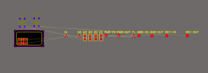
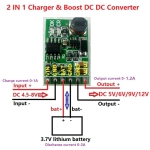
I could totally use a normal USB powerbank to drive it but a single lipo could not power the camera directly, so I wondered if modifying a powerbank to output 12V and having 2S LiPo in the camera was possible…but also a bit insane, to be honest. After much wondering and a bit of counsel, I found this tiny little board:
And at first I was going to use it as 5Vin-5Vout, but then I realized, the video board power consumption was not the same! @5V it’s about 3W, whereas @12V is 2W!, that’s a huge difference. So I ordered one that would output 12V. As for the LiPo power, I made a quick sketch to see what kind of space I had avaliable in the camera:
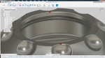
Bottom rectangle is the video board. Middle rectangle with some protrusions is the DC-DC board, and the rectangle at an angle is about the leftover space I could use to put a battery in there. Volume is about 20x6x32mm, wich is not a huge amount of space.
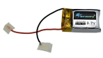
I tried hard to find a battery that would maximise the power I could fit in, but in the end I had to settle down with a meagre 180mAh micro Li-Po. Fun thing tho, when I made the rough calculations as to how much would that last, using a very convervative 80% efficient DC-DC, it gave about 14 minutes of runtime. Given I was aiming for 5 minutes, I am exctatic that it can double that recording time. (I prefer to take that number with a grain of salt and assume it is going to just not be as good, even with the 20% losses. Also, current consumption from the battery should be about 600mA, wich is a discharge of about 3.3C, not a level that should destroy the battery easily.
For details on the magnetic power supply connection, please, refer to this post.
FABRICATION
When building something like this, it’s not always straightforward what should be made in wich way.
When I was designing the camera, I kept telling myself that the shape should be manufacturable using conventional tools, and I kept looking at building the body in halves, so the pieces would be machinable from both sides. But as I continued working, I found myself distancing from that rapidly until I effectively stopped fighting the concept and embraced the truth. I wanted a monocoque body for the camera so it would be easier to seal, and I would need it 3D printed so it could have the shapes I wanted, instead of concessions for ease of manufacturability. It should not matter that much, in the end I’ll be making what, 1 to 5 of these? (various helmets, spares, occasional gift for a friend, tops).
So, I settled on having the body of the camera, frontal clamp/face and camera gimball, 3D printed in SLA resin. Luckily for me, I quickly found someone willing to print those for me at a reasonable price I could afford. The aluminium sideplate I can CNC machine at home with little trouble.
By now, some people might be wondering how is that camera supposed to be attached to the helmet. I did ponder for a while on making it attachable to a GoPro latch, but that would have increased the stickout of the camera by a noticeable margin, negating a good amount of the effort put in making it streamlined. I also considered designing a custom low profile mount, and evaluated a few different approaches, but in the end, I opted for the easiest route, attach the damn thing to the helmet directly. Here’s a list of reasons:
Single use: I only own one helmet, it’s not like I’m going to interchange the camera around.
Security: with direct attachment there are less points of failure.
Non commercial: This is for me, and there are no plans to release this as a product, so I can do whatever I want.
Also, embedded in the thoughts about manufacturing, I considered the effects of the camera during a crash. With a very resistant body and attachment system, you risk them snatching into something while crashing and hurting you more than otherwise not having those stickouts. So this camera is thought as a frangible element. In the event of a helmet collision where the camera is in the middle, the resin body will just shatter and be gone easily. If you crashed hard enough for the microSD card to be destroyed in the process, probably you have greater problems than saving the footage of the crash.
This is the end of part I. Part II will feature the SLA printed body, control button circuit/PCB, sideplate-heatsink and internal power supply and drive, so, the finished camera, so to speak.
So, I have been using this camera to record my rides for a bit now:
But, you see, I’m not the type of biker that enjoys twisty mountain passes. I like long stretches of road and covering long distances. However, with that, comes the added cost of time.
The F9 type camera can record about 2.5h of your ride, but then that’s it. It can, theoretically, record while powered, but to do that, you must remove the back dust protector and put a flimsy connector in the back, wich I don’t personally trust it would hold well over time with the cable weight and/or snags.
But damn, I still want to record longer runs! (easy, just buy a second camera)
But you are reading a post, so already know I just did not do that, did I?
Some time ago, I had already bought a second camera, but for completely different reasons. That one was dismantled shortly after receiving it, so I could explore the innards. That left me with spare parts, that, as it happens, came in handy afterwards.
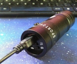
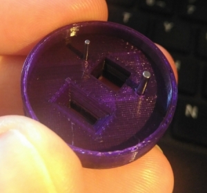
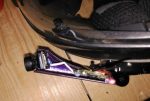
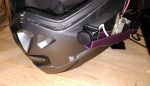
So, I was wondering about how to add external power to the camera, and I happened to nottice that the frontal ring that holds the glass, shared the same thread with the rear protector, thus giving me a nice ring clasp for a cable adaptor:
With that, I started looking for the special connector, called EC-6E, but that was nowhere to be found, so in the end I resorted to dismantling an existing cable:
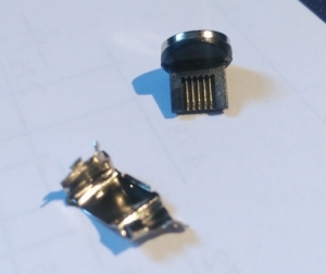
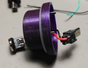
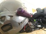
At this point, I was about to use a barrel jack to power this thing up, altough I was slightly worried that at the first yank, something was going to get broken. But then I remembered I had this magical magnetic USB connector adapter for phones.
I was pretty sure I could disassembly it enough to get the power out for my own purposes:
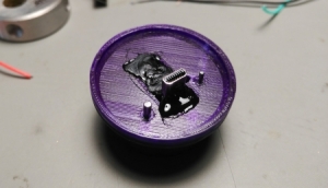
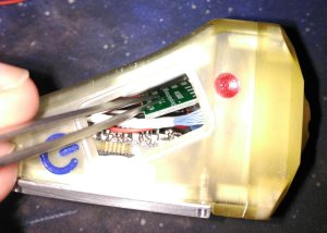
As said, it was just as easy as carefully removing the metal shield to acces the power pins (other pins not connected to anything):
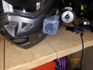
One thing to take into account was twist motion when screwing the back cover. That could put very high forces in the connector, wich would break in no time. Luckily for me, the camera has a pair of holes that happened to accept a 1.5 and 1mm pins I could use as anti-twist mechanism:
With that, I modelled the back part that would do the following:
Hold the EC-6E in place.
Prevent twist.
Hold the magnetic latch.
Be at least as hermetic as the original cover.
It took me 4 tries until I perfectly located the anti-rotation pins, but there was no good way to measure the placement directly (yet, I have a future solution for that)
Once that was ready:
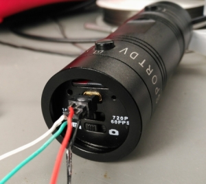
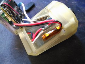
Solder the cable through:
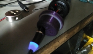
And test:
Hotglue everything in place:
That’s not my best job, but noone has to see that while in use.
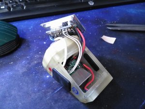
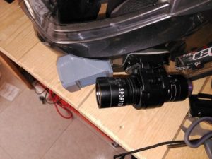
As an afterthought, I also made a second adaptor that could house a micro-SD card inside. Since the F9 can only use 32Gb max, but now the recording time is extended well past that size, it was a convenient place to put the card, for the small price of it being 5mm longer:
And with that, I went recording with some acquaintances:
It was on that ride that I confirmed I’m not a tight corner person. It was an awful experience that I did not enjoy at all, a shame, because the views where spectacular. (The descent was a bit better, as I’m used to that with my bicycle, but still, I would have preferred to pedal that down rather than ride my motorbike… ¯\_(ツ)_/¯


 (sound warning!)
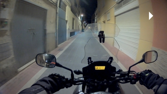


 I tried hard to find a battery that would maximise the power I could fit in, but in the end I had to settle down with a meagre 180mAh micro Li-Po. Fun thing tho, when I made the rough calculations as to how much would that last, using a very convervative 80% efficient DC-DC, it gave about 14 minutes of runtime. Given I was aiming for 5 minutes, I am exctatic that it can double that recording time. (I prefer to take that number with a grain of salt and assume it is going to just not be as good, even with the 20% losses. Also, current consumption from the battery should be about 600mA, wich is a discharge of about 3.3C, not a level that should destroy the battery easily.