Excerpt from “It’s been a long while II”, because I’m lazy:
Using moshisoft, whatever version, is just a pain in the ass for other than engraving (remember, you bought a ENGRAVING machine, it didn’t say anything about being a real cutter). Engraving tough, is quite nice and fast. You just upload a bmp, and BANG there you go.
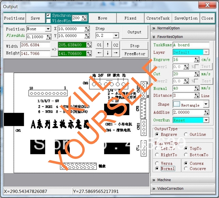
Frankly, it’s engraving properties are quite good for me, but I won’t miss all of them:
- It can’t engrave more than 200×200 (machine will go haywire). (why would you want to?)
- Can’t reliably cut DXF’s, it will ALWAYS move the final vertex from each separate piece, to the “center”.
When doing simple pieces, is just annoying, but keep in mind, it does not snap to grid or vertex, so placing them again won’t have any precision. Just don’t think about tons of pieces. - Software key (it has a hardware key) might reset amidst job, for no reason whatsoever.
- Program may change language for no reason, and try to display one you don’t have an interpreter for. (luckily, I remembered where where the options I needed, but THAT was insane…)
Software VS. Ports VS. Price:
At this stage, you might be wondering “What options do I have”? Well, I think you might have too many. XD
- The expensive one:
Mach3 + USB interface board (and you still need the drivers themselves)
- The somewhat cheaper one:
Mach3 + parallel port interface + stepper drivers
- Even cheaper:
Kcam + parallel port interface + stepper drivers
- Cheapest:
Linux CNC software + homemade electronics.
Since I’m not much of a Linux guy, I was left with the two middle options, and you can guess wich one I picked up, can you?
Kcam, the little software that works (most of the time*).
It might not be the most advanced software and has some limitations wich I would change, but otherwise, it works for controlling a laser.

Not my screenshot.
It is interesting to comment some things, tough:
It doesn’t have a specific pin to control the laser so you must use a bit of a trick, with it. You enable “Z single step”, and (me at least) I used the direction pin of the Z axis as laser control. I had set it to activate the laser on 5V from pin 4 (I just like the settings to be in accordance with their function (5v-ON, 0V-OFF)
However, and this is quite IMPORTANT, the parallel port has it’s own mind when you switch on the computer, and you must observe how the pins are set, as you don’t want your laser to start firing for no reason, do you?.
Mine, had pin 4 ON all the time, until you powered it off through software, so I had to negate the activation of the laser. I changed the pin to one that doesn’t change state on power-up.

*I’m using an old version, so I haven’t had any experience with the latest updates, it might be better it might be worse.
Version 40047 (last one to work in Win2k) specifics:
- It can’t understand partial circles (includes chamfering), so it will draw a line between start and endpoints. (complete circles are OK)
Solution: -Explode- all the drawing and then -join polyline-, it will convert curves to linear segments, and you’re good to go. I use DoublecadXT, wich doesn’t allow me to change how many segments I want when converting, so on big circles, it does show the individual segments. You have two half solutions there (apart of augmenting the segment count in your program of preference).
-> For circles, draw polygons with a high facet count, treat them as circles.
-> For curved lines, draw splines by fit points, and then explode, it will give nice and smooth curves. - If you change engraving/cutting speed sometimes it doesn’t acknowledge the speed change, so you must compulsively compile (XD!) before starting a job.
Aaand this is all I have to say about Software…you know, I’m more of a hardware guy.
Next post (whenever that is) in the series:
Calibration
Because not all rulers are the same, and why your first piece should be one.